 |
For an interferometer, there are two quantities of interest
(i) the delay difference between the signals reaching the two arms
of the interferometer (
![]() ),
where
),
where ![]() and
and ![]() are the propagation delays
for the two arms of the interferometer, and
(ii) the phase difference between the signals reaching the two arms
of the interferometer (
are the propagation delays
for the two arms of the interferometer, and
(ii) the phase difference between the signals reaching the two arms
of the interferometer (
![]() ), where
), where ![]() and
and ![]() are the excess
path lengths for the two arms of the interferometer. Generally
are the excess
path lengths for the two arms of the interferometer. Generally ![]() is small compared to the coherence bandwidth of the signal and can be
ignored to first order, however
is small compared to the coherence bandwidth of the signal and can be
ignored to first order, however ![]() could be substantial.
could be substantial.
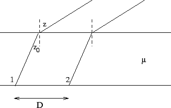
In a homogeneous plane parallel ionosphere with refractive
index ![]() (see Figure 16.1), we have from Snell's
law
(see Figure 16.1), we have from Snell's
law
![]() . The observed geometric delay is
. The observed geometric delay is
![]() , since the group velocity is
, since the group velocity is ![]() . From
Snell's law therefore,
. From
Snell's law therefore,
![]() , the same as would have
been observed in the absence of the ionosphere.
A homogeneous plane parallel ionosphere hence produces no net effect
on the visibilities, even though the apparent position of the source has
changed. In the case where the interferometer is located outside the slab,
there is neither a change in the apparent position nor a change in the
phase, as is obvious from the geometry. This entire analysis holds for
a stratified plane parallel ionosphere (since it is true for every individual
plane parallel layer). However, in the real case of a curved ionosphere,
with a radial variation of electron density, then neither the change
in the apparent position nor
, the same as would have
been observed in the absence of the ionosphere.
A homogeneous plane parallel ionosphere hence produces no net effect
on the visibilities, even though the apparent position of the source has
changed. In the case where the interferometer is located outside the slab,
there is neither a change in the apparent position nor a change in the
phase, as is obvious from the geometry. This entire analysis holds for
a stratified plane parallel ionosphere (since it is true for every individual
plane parallel layer). However, in the real case of a curved ionosphere,
with a radial variation of electron density, then neither the change
in the apparent position nor ![]() are zero even outside
the ionosphere. Effectively, the direction of arrival of the rays
from the distant source appears to be different from the true
direction of arrival (as illustrated in Figure 16.2)
and unlike in the plane parallel case this is not exactly canceled out
by the change in the refractive index. If
are zero even outside
the ionosphere. Effectively, the direction of arrival of the rays
from the distant source appears to be different from the true
direction of arrival (as illustrated in Figure 16.2)
and unlike in the plane parallel case this is not exactly canceled out
by the change in the refractive index. If ![]() is the difference
between the true direction and apparent directions of arrival, then
one can compute that
is the difference
between the true direction and apparent directions of arrival, then
one can compute that
| (16.3.5) |