 |
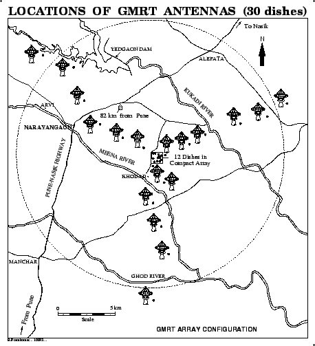
The GMRT has a hybrid configuration, (see Figure 18.1)
with 14 of its antennas randomly distributed in a central region
(![]() km across), called the central square. The distribution of antennas
in the central square was deliberately ``randomized'' to avoid grating lobes. The antennas in
the central square are labeled as Cnn, with nn going from 00 to 14
(i.e. C00, C01,....C14)18.1. The remaining antennas are distributed in a roughly Y shaped
configuration, with the length of each arm of the Y being
km across), called the central square. The distribution of antennas
in the central square was deliberately ``randomized'' to avoid grating lobes. The antennas in
the central square are labeled as Cnn, with nn going from 00 to 14
(i.e. C00, C01,....C14)18.1. The remaining antennas are distributed in a roughly Y shaped
configuration, with the length of each arm of the Y being ![]() km.
The maximum baseline length between the extreme arm antennas
is
km.
The maximum baseline length between the extreme arm antennas
is ![]() km. The arms are called the ``East'' ``West'' and
``South'' arms and the antennas in these arms are labeled E01..E06,
W01..W06 and S01..S06 for the east, west and south arm respectively.
km. The arms are called the ``East'' ``West'' and
``South'' arms and the antennas in these arms are labeled E01..E06,
W01..W06 and S01..S06 for the east, west and south arm respectively.
The central square antennas provide a large number of relatively short baselines. This is very useful for imaging large extended sources, whose visibilities are concentrated near the origin of the UV plane. The arm antennas on the other hand are useful in imaging small sources, where high angular resolution is essential. A single GMRT observation hence yields information on a variety of angular scales.