The ![]() ratio for the GMRT antennas was fixed at the
value
ratio for the GMRT antennas was fixed at the
value ![]() based both on structural design issues as well as preliminary
studies of various feeds radiation patterns. Since the antennas are
to work at meter wavelengths prime focus feeds were preferred. Cassegrain
feeds at meter wavelengths would result in impractically large secondary
mirrors (the mirror has to be several
based both on structural design issues as well as preliminary
studies of various feeds radiation patterns. Since the antennas are
to work at meter wavelengths prime focus feeds were preferred. Cassegrain
feeds at meter wavelengths would result in impractically large secondary
mirrors (the mirror has to be several ![]() across) and concomitant
large aperture blockage.
across) and concomitant
large aperture blockage.
Six bands of frequencies had been identified [1] for
the GMRT observations. It was deemed essential to be able to change
the observing frequency rapidly, and consequently the feeds had to
mounted on a rotating turret placed at the prime focus. If one were
to mount all the six feeds on a rotating hexagon at the focus, the
adjacent feeds will be separated by ![]() . If one wants to
illuminate the entire aperture, then one has to have a feed pattern
that extends at least up to the subtended angle of the parabola edge,
which is
. If one wants to
illuminate the entire aperture, then one has to have a feed pattern
that extends at least up to the subtended angle of the parabola edge,
which is
![]() (Note that
(Note that
![]() , Figure 19.1). Hence
this arrangement of feeds would cause the one feed to ``see'' the
feeds on the adjacent faces. It was decided therefore to mount the
feeds in orthogonal faces of a rotating cube. Since one needs six
frequency bands, this leads to the constraint that at least two faces
of the turret should support dual frequency capability. For astronomical
reasons also dual frequency capability was highly desirable.
, Figure 19.1). Hence
this arrangement of feeds would cause the one feed to ``see'' the
feeds on the adjacent faces. It was decided therefore to mount the
feeds in orthogonal faces of a rotating cube. Since one needs six
frequency bands, this leads to the constraint that at least two faces
of the turret should support dual frequency capability. For astronomical
reasons also dual frequency capability was highly desirable.
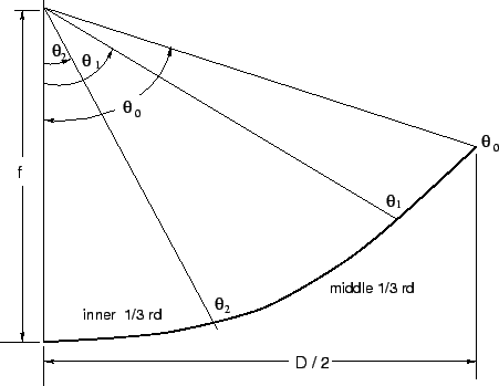
One specific aspect of GMRT design is the use of mesh panels
to make the reflector surface[1]. Since the mesh is not perfectly reflective,
transmission losses thorough the mesh have to be taken into account.
Further, the expected surface errors of the mesh panels was ![]() mm.
This implies that the maximum usable frequency is
(see Section 19.2)
mm.
This implies that the maximum usable frequency is
(see Section 19.2) ![]() MHz, independent of the
transmission losses of the mesh. (Incidentally, since the mean-spacing
of feed-support legs,
MHz, independent of the
transmission losses of the mesh. (Incidentally, since the mean-spacing
of feed-support legs,
![]() m, the lowest usable frequency
is around 6 MHz).
m, the lowest usable frequency
is around 6 MHz).
Several analytical methods exist in literature to compute the
transmission loss through a mesh as a function of the cell size, the wire
diameter and the wavelength of the incident radiation. The one chosen for
our application is has good experimental support [2,3]. At the GMRT,
the mesh size is ![]() mm for the central 1/3 of the dish,
mm for the central 1/3 of the dish,
![]() mm of the middle 1/3 of the dish and
mm of the middle 1/3 of the dish and ![]() mm for
the outer 1/3 of the dish. The wire diameter is
mm for
the outer 1/3 of the dish. The wire diameter is ![]() mm. The
transmission loss for at two fiducial wavelengths for these various
mesh sizes is given in Table 19.2.
mm. The
transmission loss for at two fiducial wavelengths for these various
mesh sizes is given in Table 19.2.
|
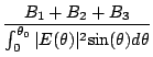
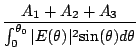
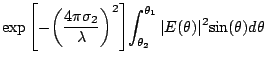
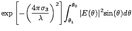
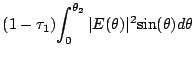
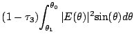
Each section of the dish not only has a separate mesh size but
also a separate surface rms error. If we call these rms surface errors
![]() and the respective transmission
losses (at some given wavelength)
and the respective transmission
losses (at some given wavelength)
![]() ,
then the surface rms efficiency given by Eqn 19.4.15 has
to be altered to a weighted rms efficiency:
,
then the surface rms efficiency given by Eqn 19.4.15 has
to be altered to a weighted rms efficiency:
 |
![$\displaystyle {\exp{\left[ -{\left( {\frac{4{\pi}{{\sigma}_1}}{\lambda}}
\right...
...]}}
{\int_{0}^{{\theta}_2}{\vert E({\theta})\vert^2{\sin({\theta})} d{\theta}}}$](img1563.gif) |
(19.5.17) | ||
 |
(19.5.18) | ||
 |
(19.5.19) | ||
 |
The transmission loss gives a corresponding mesh-leakage or
mesh-transmission efficiency,
![]() , which is
given by
, which is
given by
 |
(19.5.21) | ||
 |
(19.5.22) | ||
 |
(19.5.23) | ||
Efficiencies computed for the different GMRT feeds (using their measured pattern, being the input) are given in Table 19.4.