next up previous contents
Next: GMRT Feeds Up: Design Specifications for the Previous: Design Specifications for the   Contents


Secondary Patterns

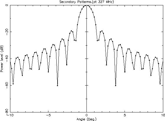
The antenna pattern at 327 MHz as computed using geometric optics is shown in Figure 19.5. More rigorous analytical models (the Uniform Theory of Diffraction [7]) gives the pattern shown in Figure 19.6.

Figure 19.5: Computed pattern (using geometric optics) of a GMRT antenna at 327 MHz.
\begin{figure}\centerline{ \psfig{figure=scpi3eCor.ps,width=150mm} }\end{figure}

Figure 19.6: Computed pattern (using uniform theory of diffraction) of a GMRT antenna at 327 MHz.
\begin{figure}\centerline{\psfig{figure=secn327Cor.ps,width=150mm}}\end{figure}

There is a pronounced difference seen at the side-lobe structures between these two models, while the primary beam shows near-identical shapes and the HPBW value matches to a second decimal accuracy. The computed HPBW also agrees to within measurement errors with the observed HPBW of the actual GMRT antennas.


next up previous contents
Next: GMRT Feeds Up: Design Specifications for the Previous: Design Specifications for the   Contents
NCRA-TIFR