This feed employs four dipoles in a ``boxing ring''
configuration, placed above a plane reflector. The unique feature of the
dipole is that it is wide-band i.e. has an octave bandwidth. It is
a folded dipole with each arm being a ``thick'' dipole. A dipole
is called 'thin' when its diameter,
![]() . For such
dipoles a sinusoidal current distribution can be assumed for the
computation of input impedance and related radiation parameters.
. For such
dipoles a sinusoidal current distribution can be assumed for the
computation of input impedance and related radiation parameters.
Thin dipoles have narrowband radiation characteristics.
One method by which its acceptable operational bandwidth can be increased
is to decrease the ![]() ratio. For example, an antenna with a
ratio. For example, an antenna with a
![]() has an acceptable bandwidth of about 3%, while
an antenna of the same length but with a
has an acceptable bandwidth of about 3%, while
an antenna of the same length but with a
![]() has a
bandwidth of about 30%. By folding the dipole, one gets a four-fold
increase in input impedance compared to a simple dipole. The 150 MHz
feed also has a transmission line impedance transformer coupled to the
excitation point [9].
has a
bandwidth of about 30%. By folding the dipole, one gets a four-fold
increase in input impedance compared to a simple dipole. The 150 MHz
feed also has a transmission line impedance transformer coupled to the
excitation point [9].
Traditionally crossed-dipoles are used to give
sensitivity to both polarizations. However since a crossed-dipole
configuration in this design would be extremely cumbersome, a ``boxing
ring'' design was instead chosen. Here one pair of dipoles at
![]() spacing provides sensitivity to one linear polarization.
Another pair orthogonally oriented with respect to the first pair gives
sensitivity to the orthogonal polarization. The overall dimensions of
the feed are:
spacing provides sensitivity to one linear polarization.
Another pair orthogonally oriented with respect to the first pair gives
sensitivity to the orthogonal polarization. The overall dimensions of
the feed are:
The dipoles have an ![]() ratio of 6.48, and
the phase center was determined to be at a height of 100 mm above the
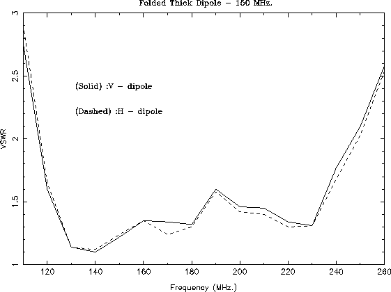
reflector. The feed's impedance bandwidth can be seen on the VSWR plot
of Figure 19.8
ratio of 6.48, and
the phase center was determined to be at a height of 100 mm above the
reflector. The feed's impedance bandwidth can be seen on the VSWR plot
of Figure 19.8
The usable bandwidth for a feed is given approximately by
the range for which SWR ![]() . By this criteria, the frequency
coverage of the 150 MHz feed is from 117 MHz to 247 MHz,
i.e. a bandwidth of 130 MHz, or 86% bandwidth. The radiation pattern
gives an edge taper,
. By this criteria, the frequency
coverage of the 150 MHz feed is from 117 MHz to 247 MHz,
i.e. a bandwidth of 130 MHz, or 86% bandwidth. The radiation pattern
gives an edge taper, ![]() dB.
dB.
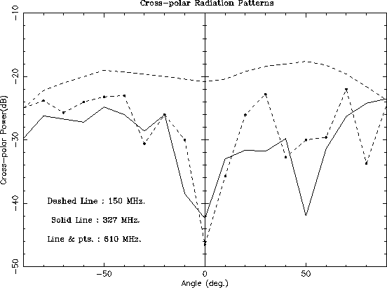
One undesirable feature of this feed is the high value of cross-polarization, as compared to that at other frequencies (see Figure 19.9)19.4. The cross-polar peak for 150 MHz. is -17 dB and the on-axis cross polarization is also at about the same level.
 |
One-pair of outputs from the dipoles which are parallel to each other are connected to a power-combiner, whose output goes to one port of the quadrature hybrid (which adds two linear polarized signals to yield one circular polarized signal). Similarly the orthogonal pair of dipoles are connected to the other port of the hybrid. Both the power combiners and the quadrature hybrid are mounted inside one of the front-end chassis, placed behind the feed.