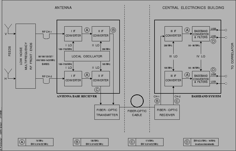
The GMRT receiver chain is shown schematically in Figure 21.1. The first block is the multi-frequency front end. This is located in a rotating turret at the prime focus. All the feeds and low noise RF front-ends have been configured to receive dual polarization signals. Lower frequency bands (from 50 to 610 MHz) have dual circular polarization channels, i.e. left hand circular and right hand circular polarizations which have been labelled as CH1 and CH2 respectively. The L-band (1000-1450 MHz) system has dual linear polarization channels, i.e. vertical and horizontal polarizations (also labelled CH1 and CH2 respectively).
The first local oscillator (I LO, situated at the base of the antenna, inside a shielded room) converts the RF band to an IF band centered at 70 MHz. After passing the signal through a bandpass filter of selectable bandwidth, the IF at 70 MHz is then translated (using II LO) to a second IF at 130 MHz and 175 MHz for CH1 and CH2, respectively. The maximum bandwidth available at this stage is 32 MHz for each channel. This frequency translation is done so that signals for both polarizations can be frequency division multiplexed onto the same fiber for transmission to the CEB.
At the CEB, these signals are received by the Fiber-Optic Receiver and the 130 and 175 MHz signals are then separated out and sent for base band conversion. The baseband converter section converts the 130 and 175 MHz IF signals first to 70 MHz IF (using III LO), these are then converted to upper and lower side bands (each at most 16 MHz wide) at 0 MHz using a tunable IV LO. The various local oscillators and baseband system are discussed in more detail in Chapter 23. There are also two Automatic Level Controllers (ALCs) in the receiver chain (not shown in Figure 21.1 but discussed in more detail below). The first is just before the Fiber Optic transmitter and the second is at the output of the baseband unit.