| (22.2.1) |
A block diagram of the GMRT optical transmitter is shown in Figure 22.3. The optical signal that is transmitted down the fiber is generated by appropriately modulating a laser diode, which is essentially a forward biased p-n junction diode (typically InGaAsP). The edges of the p-n diode are cleaved such that they act as mirror resonators. Photons travel between the mirrors and for the wavelengths which bear the following relationship with distance between the mirrors, longitudinal mode oscillations occur:
| (22.2.1) |
where ![]() is an integer,
is an integer, ![]() is the length of cavity,
is the length of cavity, ![]() is the refractive
index of the medium and
is the refractive
index of the medium and ![]() is the longitudinal mode frequency.
An active medium within the diode provides positive feedback to these
photons thus providing amplification.
is the longitudinal mode frequency.
An active medium within the diode provides positive feedback to these
photons thus providing amplification.
The laser used in GMRT is of multi-mode type. The (nominal) peak
wavelength is 1300 nm and spectral width is 2 nm (rms). Multi-mode
lasers are appropriate for ``low'' (i.e ![]() GHz) bandwidth
applications. At higher bandwidths multi-mode lasers are not acceptable,
since they lead to more dispersion and also to inter-modulation
products. Inter-modulation (IM) products are essentially a particular
kind of non linear response. When two pure sine waves are fed to a
non ideal device, the output will have additional frequency products
that are related to the frequencies of the two input
sine waves. These are called IM products of different orders.
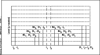
Figure 22.4 shows a few low order inter-modulation products.
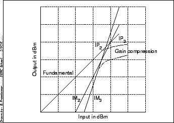
The amplitudes for these products is a non linear function of the
amplitudes of the input sine waves (see Figure 22.5). The
figure also illustrates gain compression where beyond a critical
input power the output is no longer linearly related to the input,
even at the fundamental frequency.
GHz) bandwidth
applications. At higher bandwidths multi-mode lasers are not acceptable,
since they lead to more dispersion and also to inter-modulation
products. Inter-modulation (IM) products are essentially a particular
kind of non linear response. When two pure sine waves are fed to a
non ideal device, the output will have additional frequency products
that are related to the frequencies of the two input
sine waves. These are called IM products of different orders.
Figure 22.4 shows a few low order inter-modulation products.
The amplitudes for these products is a non linear function of the
amplitudes of the input sine waves (see Figure 22.5). The
figure also illustrates gain compression where beyond a critical
input power the output is no longer linearly related to the input,
even at the fundamental frequency.
 |
 |
The laser intensity is modulated according to the signal that is to be transmitted, i.e at the GMRT one uses analog modulation. There are two types of analog modulation, direct and external. In direct modulation the signal is applied directly to an optical carrier generator whose light output varies as per the applied signal. In external modulation the modulating signal is applied outside the device for changing the intensity of the light carrier. In GMRT the simpler direct modulation method is employed.
In the linear regime, the optical power output, ![]() by
the laser is proportional to the input current
by
the laser is proportional to the input current ![]() , the constant
of proportionality is the slope of the characteristic curve and is
usually denoted by
, the constant
of proportionality is the slope of the characteristic curve and is
usually denoted by ![]() .
.