 |
User commands for various antennas are processed by ONLINE running on a UNIX workstation and are sent to the COMH via the PCROUTER. The PCROUTER acts as a buffer and accepts the TCP/IP data on a 10/100 Mbps (i.e. a standard ethernet) link, strips the TCP/IP header and sends the data to COMH on a 38.4 kbps link. This uses a standard RS232-C link on the PC side and a conversion to RS 422 signals (differential TTL signals) on the COMH side.
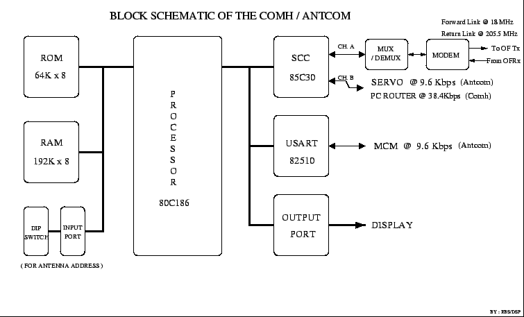
COMH (see Figure 24.2) is basically an 80C186, 16 bit micro-controller based card, which works at a clock speed of 6 MHz. This card also contains a Zilog 85C30 dual channel communication controller. The two channels are respectively for SDLC/HDLC communication at 125 kbps (for communication with the ANTCOMs at the different antennas) and a asynchronous communication at 38.4 kbps (for communicating with the PCROUTER). COMH also has an Intel 29C17 CODEC (voice coder-decoder) to handle voice communication at 62.5 kbps, circuitry for digital Phase Lock Loop and other combinational logic to handle clock recovery and bit interleaving functions, as well as FSK modem chips NE 5080 and NE 5081 to handle FSK modulation and demodulation. COMH multiplexes command data, digitized voice, synchronization pulses, dial pulses and two aux channels into a single bit stream. This bit stream is then converted (via FSK, see section 24.4.1 for details) to an analog signal at 18 MHz.
 |
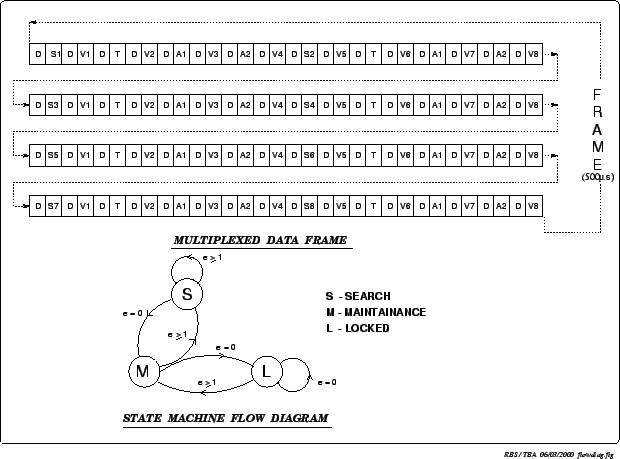
The block diagram for this multiplexing of voice and data is shown in Figure 24.3. The structure of the multiplexed bit interleaved data frame is shown in Figure 24.4. At the bottom of this figure is shown the flow diagram for the synchronous detector state machine.
 |
The FSK analog signal is sent via the fiber optic link to the ANTCOM at the antenna base. The ANTCOM has the same circuitry as COMH but unlike COMH it handles two serial communication links (using an INTEL 82510 Communication Controller) i.e. the ANTCOM-MCM communication link and a serial link to the Servo Control Computer (SCC). ANTCOM demodulates the FSK signal into 250 kbps data, regenerates the 250 kHz clock using a digital Phase Lock Loop, looks for sync bits and if it finds a match with no error or one bit error then it demultiplexes the data into command, voice, dial pulse and aux data and passes each to the appropriate circuit for further processing (see Figure 24.3). The ANTCOM communicates with and controls the various subsystems in the antenna (other than the servo subsystem for which there is the dedicated SCC) via the MCM cards. A block diagram of the MCM card is shown in Figure 24.5. The MCM card is a general purpose 80C535 Micro-controller based card which provides 16 TTL Control O/Ps and monitors upto 64 analog signals. It also has an RS485 communication link for communicating with the ANTCOM.
For the return link, the ANTCOM takes the monitoring information from SCC, MCMs and FPS forms a packet of SDLC/HDLC data and multiplexes with voice, hook status and aux channels into a single bit stream. This bit stream is converted into an FSK analog signal at 4.5 MHz, which is then up converted to 205.5 MHz using the regenerated 201 MHz as the LO (see Figure 24.8). This analog signal is sent along with the astronomical signals to the CEB. At the CEB thirty CEBCOMs (one for each antenna) demodulate the FSK signal to convert it back into a digital 250 kbps data stream which is passed on to COMH via a 32 way multiplexer (MUX 32) card. The voice signals from the antennas are routed to the EPABX (telephone exchange) system. The block diagram for this telephonic communication is shown in Figure 24.6. The voice signals are digitized using an INTEL 29C17 CODEC IC using a 7.8 kHz clock to produce a 62.5 kbps data stream. The CODEC uses ``A law" for data companding/expanding.