 |
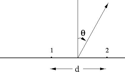
We begin by deriving the far field radiation pattern for the case of the simplest
array, two isotropic point source elements separated by a distance d, as shown
in Figure 6.1. The net far field in the direction ![]() is given as
is given as
| (6.2.1) |
For the case of ![]() and
and ![]() , the field pattern of
this array shows sinusoidal oscillations for small variations of
, the field pattern of
this array shows sinusoidal oscillations for small variations of ![]() around
zero, with a period of
around
zero, with a period of ![]() . Non-zero values of
. Non-zero values of ![]() simply shift
the phase of these oscillations by the appropriate value.
simply shift
the phase of these oscillations by the appropriate value.
If the individual elements are not isotropic but have identical directional
patterns, the result of eqn 6.2.2 is modified by replacing
![]() with the element pattern,
with the element pattern, ![]() . The final pattern is given by
the product of this element pattern with the
. The final pattern is given by
the product of this element pattern with the ![]() term which represents
the array pattern. This brings us to the important principle of pattern multiplication
which can be stated as : The total field pattern of an array of nonisotropic
but similar elements is the product of the individual element pattern and the
pattern of an array of isotropic point sources each located at the phase centre
of the individual elements and having the same relative amplitude and phase,
while the total phase pattern is the sum of the phase patterns of the individual
elements and the array of isotropic point sources. This principle is used
extensively in deriving the field pattern for complicated array configurations,
as well as for designing array configurations to meet specified field pattern
requirements (see the book on ``Antennas'' by J.D. Kraus (1988) for more details).
term which represents
the array pattern. This brings us to the important principle of pattern multiplication
which can be stated as : The total field pattern of an array of nonisotropic
but similar elements is the product of the individual element pattern and the
pattern of an array of isotropic point sources each located at the phase centre
of the individual elements and having the same relative amplitude and phase,
while the total phase pattern is the sum of the phase patterns of the individual
elements and the array of isotropic point sources. This principle is used
extensively in deriving the field pattern for complicated array configurations,
as well as for designing array configurations to meet specified field pattern
requirements (see the book on ``Antennas'' by J.D. Kraus (1988) for more details).