 |
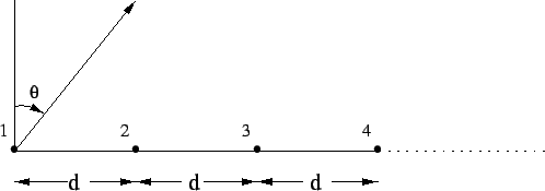
We now consider the case of a uniform linear array of n elements of equal amplitude,
as shown in Figure 6.2. Taking the first element as the phase reference,
the far
field pattern is given by
| (6.2.3) |
The field pattern in eqn 6.2.4 has a maximum value of ![]() when
when
![]() .
The maxima at
.
The maxima at ![]() is called the main lobe, while the other maxima are called
grating lobes. For
is called the main lobe, while the other maxima are called
grating lobes. For ![]() , only the main lobe maxima maps to the physically
allowed range of
, only the main lobe maxima maps to the physically
allowed range of
![]() .
By suitable choice of the value of
.
By suitable choice of the value of ![]() , this maxima can be ``steered'' to
different values of
, this maxima can be ``steered'' to
different values of ![]() , using the relation
, using the relation
![]() .
For example, when all the elements of the array are in phase (
.
For example, when all the elements of the array are in phase (![]() ), the
maximum occurs at
), the
maximum occurs at ![]() . This is referred to as a ``broadside'' array.
For a maximum along the axis of the array (
. This is referred to as a ``broadside'' array.
For a maximum along the axis of the array (
![]() ),
),
![]() is required, giving rise to an ``end-fire'' array.
The broadside array produces a disc or fan shaped beam that covers a full 360
is required, giving rise to an ``end-fire'' array.
The broadside array produces a disc or fan shaped beam that covers a full 360![]() in the plane normal to the axis of the array. The end-fire array produces a cigar
shaped beam which has the same shape in all planes containing the axis of the array.
For nonisotropic elements, the element pattern also
needs to be steered (electrically or mechanically) to match the direction of its
peak response with that of the peak of the array pattern, in order to achieve the
maximum peak of the total pattern.
in the plane normal to the axis of the array. The end-fire array produces a cigar
shaped beam which has the same shape in all planes containing the axis of the array.
For nonisotropic elements, the element pattern also
needs to be steered (electrically or mechanically) to match the direction of its
peak response with that of the peak of the array pattern, in order to achieve the
maximum peak of the total pattern.
For the case of ![]() , the grating lobes are uniformly spaced in
, the grating lobes are uniformly spaced in
![]() with an interval between adjacent lobe maxima of
with an interval between adjacent lobe maxima of ![]() , which
translates to
, which
translates to
![]() on the
on the ![]() axis (see Figure 6.3).
axis (see Figure 6.3).
The uniform, linear array has nulls in the radiation pattern which are given by the
condition
![]() which yields
which yields
| (6.2.5) |
| (6.2.6) |
| (6.2.7) |
| (6.2.8) |
| (6.2.9) |
Such linear arrays are useful for studying sources of size ![]() radians,
as only one lobe of the pattern can respond to the source at a given time.
Also, the source should be strong enough so that confusion due to other sources in
the grating lobes is not significant. Linear grating arrays are particularly useful
for studying strong isolated sources such as the Sun.
radians,
as only one lobe of the pattern can respond to the source at a given time.
Also, the source should be strong enough so that confusion due to other sources in
the grating lobes is not significant. Linear grating arrays are particularly useful
for studying strong isolated sources such as the Sun.
 |
The presence of grating lobes (with amplitude equal to the main lobe) in the response
of an array is usually an unwanted feature, and it is desirable to reduce their levels
as much as possible. For non-isotropic elements, the taper in the element pattern
provides a natural reduction of the amplitude of the higher grating lobes. This is
illustrated in Figure 6.3. To get
complete cancellation of all the grating lobes starting with the first one, requires
an element pattern that has periodic nulls spaced ![]() apart, with the first
null falling at the location of the first grating lobe. This requires the elements
to have an aperture of
apart, with the first
null falling at the location of the first grating lobe. This requires the elements
to have an aperture of ![]() , which makes the array equivalent to a continuous
or filled aperture telescope. This can be seen mathematically by replacing
, which makes the array equivalent to a continuous
or filled aperture telescope. This can be seen mathematically by replacing ![]() in
eqn 6.2.4 by the element pattern of an antenna of aperture size
in
eqn 6.2.4 by the element pattern of an antenna of aperture size ![]() and showing
that it reduces to the expression for the field pattern of a continuous aperture of
size
and showing
that it reduces to the expression for the field pattern of a continuous aperture of
size ![]() .
.
The theoretical treatment given above is easily extended to two dimensional antenna arrays.