Radiotelescopes with a variety of antennas of different forms have been built to suit the large range of wavelengths over which radio observations are made7.1. Quasi-optical antennas such as parabolic reflectors are considered more appropriate for milli-meter and centi-meter wavelengths. At the other end of the radio spectrum, multi element arrays of dipole antennas have been preferred for meter and deca-meter wavelengths.
Early observations in radio astronomy were made using one of the two methods,
either pencil beam aerials of somewhat lower resolution to investigate the distribution
of radio emission over the sky, or interferometers to observe bright sources of small
angular size. However, the observations made during the early ![]() 's, showed that
to determine the real nature of the radio brightness distribution it is necessary to
construct pencil beam radio telescopes having beam widths of the same order as the
separation between the lobes of the interferometers then in use
's, showed that
to determine the real nature of the radio brightness distribution it is necessary to
construct pencil beam radio telescopes having beam widths of the same order as the
separation between the lobes of the interferometers then in use ![]() . An
important step towards such modern high-resolution radiotelescopes was the realisation
that in many cases even unfilled apertures, which contain all the relative positions
of a filled aperture, (``skeleton telescopes'') can be used to measure the brightness
distribution. A cross-type radio telescope, pioneered by Mills was the first to
demonstrate the principle of skeleton telescopes.
. An
important step towards such modern high-resolution radiotelescopes was the realisation
that in many cases even unfilled apertures, which contain all the relative positions
of a filled aperture, (``skeleton telescopes'') can be used to measure the brightness
distribution. A cross-type radio telescope, pioneered by Mills was the first to
demonstrate the principle of skeleton telescopes.
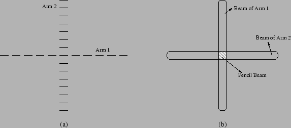
A cross consists of two long and relatively narrow arrays arranged as a
symmetrical cross, usually in the ![]() and the
and the ![]() directions, intersecting at
right angles at their centers (Figure 7.1). Each array has a fan
beam response, narrow along its length and wide in a perpendicular direction7.2. The outputs from both the arrays are amplified and
multiplied together; only sources of radiation that lie within the cross hatched
portion of Figure 7.1(b) produce a coherent signal. Thus an
effective pencil beam is produced of angular size determined solely by the
length of the two arrays. A substantial number of telescopes were constructed based
on this principle.
directions, intersecting at
right angles at their centers (Figure 7.1). Each array has a fan
beam response, narrow along its length and wide in a perpendicular direction7.2. The outputs from both the arrays are amplified and
multiplied together; only sources of radiation that lie within the cross hatched
portion of Figure 7.1(b) produce a coherent signal. Thus an
effective pencil beam is produced of angular size determined solely by the
length of the two arrays. A substantial number of telescopes were constructed based
on this principle.
 |
The Sydney University telescope was constructed as a cross with aerials
of overall dimensions approximately ![]() mile long and
mile long and ![]() ft wide (Mills et al 1963).
The mile-long reflectors are in the form of cylindrical parabolas, with a surface
of wire mesh. Line feeds for two operating frequencies of
ft wide (Mills et al 1963).
The mile-long reflectors are in the form of cylindrical parabolas, with a surface
of wire mesh. Line feeds for two operating frequencies of ![]() MHz and
MHz and ![]() MHz
were provided at their foci. The
MHz
were provided at their foci. The ![]() arm employs a fixed reflector pointing
vertically upwards and the beam is directed in the meridian plane by phasing the
dipoles of the feed. The
arm employs a fixed reflector pointing
vertically upwards and the beam is directed in the meridian plane by phasing the
dipoles of the feed. The ![]() arm is tiltable about its long axis to direct the
beam, also in the meridian plane, to intersect the
arm is tiltable about its long axis to direct the
beam, also in the meridian plane, to intersect the ![]() response pattern.
No phasing was employed in this aerial. The angular coverage was
response pattern.
No phasing was employed in this aerial. The angular coverage was ![]() on either
side of the zenith. The
on either
side of the zenith. The ![]() aperture is divided into two separate halves through
which the continuous
aperture is divided into two separate halves through
which the continuous ![]() arm passes. The total collecting area is
arm passes. The total collecting area is ![]() sq.ft.
This instrument had a resolution of approximately
sq.ft.
This instrument had a resolution of approximately ![]() at 408 MHz. This later came
to be known as the ``Mills Cross'' and is one of the earliest cross type radio telescope
built. In order to reduce cost, this telescope was built as a meridian transit
instrument.
at 408 MHz. This later came
to be known as the ``Mills Cross'' and is one of the earliest cross type radio telescope
built. In order to reduce cost, this telescope was built as a meridian transit
instrument.
Note that in a cross antenna, one quarter of the antenna provides redundant
information, since all element spacings of a filled aperture are still present if
half of one array is removed. In fact, it can be shown that the cosine response of
a ![]() array is similar to that of a full cross. Thus a survey carried out using
a
array is similar to that of a full cross. Thus a survey carried out using
a ![]() array has the same resolution as that of a survey carried out using a cross.
However it has a collecting area
array has the same resolution as that of a survey carried out using a cross.
However it has a collecting area ![]() times lower than the corresponding
cross and hence a lower sensitivity.
times lower than the corresponding
cross and hence a lower sensitivity.