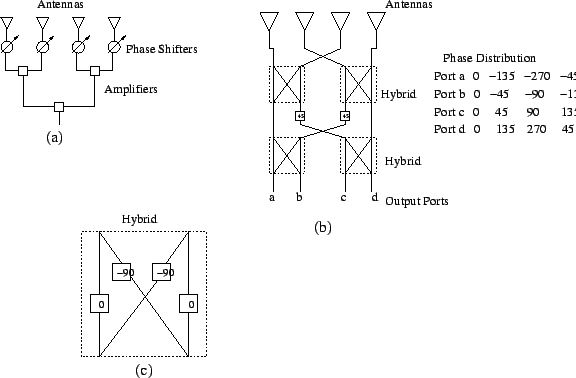
An array can be considered as a sampled aperture. When an array is illuminated by a source, samples of the source's wavefront are recorded at the location of the antenna elements. The outputs from the elements can be subjected to various forms of signal processing, where in phase and amplitude adjustments are made to produce the desired outputs. If the voltages from elemental antennas are simply added (as in the phased arrays discussed in Chapter 6), the energy received from a large portion of the sky will be rejected. When the array is illuminated by a point source this gives the beam of the array which is the Fourier transform of the aperture current distribution. A single beam instrument can use only a part of the total available time to observe each beam width of the sky. One can generate multiple independent beams in the sky by amplifying the signals from element separately and combining them with different phase shifts. Such a multiple-beam or image forming instrument can observe different directions in the sky simultaneously.
A simple linear array, which generates a single beam, can be converted to a
multiple beam antenna by attaching phase shifters to the output of each element. Each
beam to be formed requires one additional phase shifter per element. Thus an
![]() element array needs
element array needs ![]() squared phase shifters. Since the formation of a beam
is Fourier transforming the aperture distribution, this requirement of
squared phase shifters. Since the formation of a beam
is Fourier transforming the aperture distribution, this requirement of ![]() squared
phase shifters is very similar to the requirement of
squared
phase shifters is very similar to the requirement of ![]() squared multipliers for
an
squared multipliers for
an ![]() point Fourier transform. Such a network is known as a Blass network
(Figure 7.2). Similar to the fast Fourier transform, we also have
a Butler beam-forming matrix, which needs only
point Fourier transform. Such a network is known as a Blass network
(Figure 7.2). Similar to the fast Fourier transform, we also have
a Butler beam-forming matrix, which needs only ![]() elements for beam
forming. The Butler matrix uses
elements for beam
forming. The Butler matrix uses ![]() phase-lag hybrid junctions with
phase-lag hybrid junctions with ![]() fixed-phase shifters. Blass and Butler networks for a four-element array are shown
in the Figure 7.2. If the elemental spacing is
fixed-phase shifters. Blass and Butler networks for a four-element array are shown
in the Figure 7.2. If the elemental spacing is ![]() , the
butler matrix produces four beams. Although these beams overlap, they are mutually
orthogonal. Surprisingly the Butler matrix was developed before the development
of the FFT.
, the
butler matrix produces four beams. Although these beams overlap, they are mutually
orthogonal. Surprisingly the Butler matrix was developed before the development
of the FFT.
There are a number of drawbacks with multiple-beam formers, viz.
 |