 |
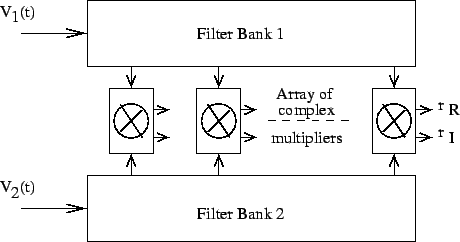
The band limited signal can be decomposed into spectral components
using a filter bank. The spectral visibility is then obtained by
separately cross correlating each filter output using a complex
correlator (see Fig. 9.3). The digital implementation of this
method is called an FX correlator (F for Fourier Transform and
X for multiplication or correlation). The GMRT correlator is an FX
correlator. A schematic of an FX correlator is shown in Fig. 9.4.
The analog voltages ![]() and
and ![]() are digitized first using ADCs.
The geometric delay in steps of the sampling intervals (integral delay)
are then compensated for. The integral delay compensated samples are
multiplied by the output of NCO for fringe stopping. The samples from
each antenna are then passed through an FFT block to realize a filter
bank. Phase gradients are applied after taking the Fourier Transform
for fractional delay compensation. The spectral visibility is then
measured by multiplying the spectral components of one antenna with the
corresponding spectral components of other antennas. These are then
integrated for some time to get an estimate of the cross correlation.
Since the Fourier transform is taken before multiplication it is called
an FX correlator. For continuum observations with an FX correlator
the visibility measured from all spectral components can be averaged after
bandpass calibration.
are digitized first using ADCs.
The geometric delay in steps of the sampling intervals (integral delay)
are then compensated for. The integral delay compensated samples are
multiplied by the output of NCO for fringe stopping. The samples from
each antenna are then passed through an FFT block to realize a filter
bank. Phase gradients are applied after taking the Fourier Transform
for fractional delay compensation. The spectral visibility is then
measured by multiplying the spectral components of one antenna with the
corresponding spectral components of other antennas. These are then
integrated for some time to get an estimate of the cross correlation.
Since the Fourier transform is taken before multiplication it is called
an FX correlator. For continuum observations with an FX correlator
the visibility measured from all spectral components can be averaged after
bandpass calibration.