Baseband System
Baseband System
At the GMRT, the dual polarized RF signals from each antenna are processed through super heterodyne receivers and finally brought to a central location for further processing. The intermediate frequency (IF) signals from each antenna are then down-converted to baseband signals and fed to the digital signal processing backend. A baseband system is used for converting the IF signal to baseband signal to get a 32 MHz bandwidth from each polarization
The baseband system contains two units, the J41 unit and the new IF conversion unit. Both these units are housed in a Plug-In-Unit (PIU). The J41 and the new IF conversion units together make up the baseband system. The units are available for a channel of 175 MHz as well as 130 MHz. These units play the key role in the down conversion of the RF signal.
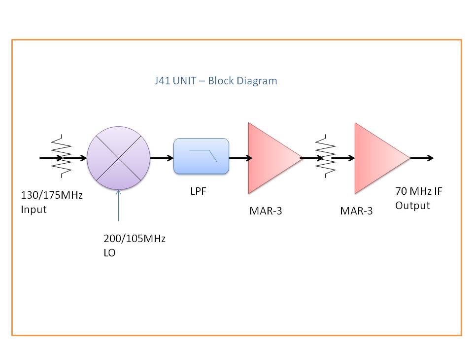
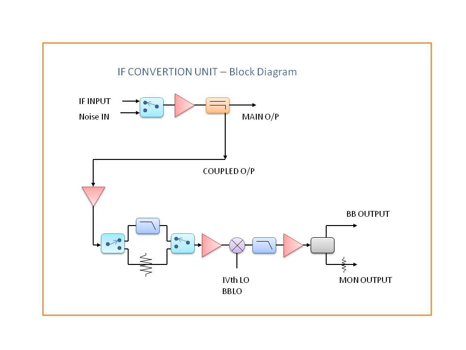
The J41 and New IF conversion basically work on the super heterodyne principle. The RF(130/175Mhz) and LO (200/105MHz) signals given to the J41 as inputs. The mixer in the J41 converts these two signals ,of frequency fif and flo , into the two new heterodyne frequencies frf + flo and frf - flo. The mixer may inadvertently produce additional frequencies such as third- and higher-order intermediation products. Ideally, the IF bandpass filter removes all but the desired IF signal at fIF. The frequency of the local oscillator fLO is set so the desired reception radio frequency fRF mixes to fIF. There are two choices for the local oscillator frequency because the dominant mixer products are at fRF ± fLO. If the local oscillator frequency is less than the desired reception frequency, it is called low side injection (fIF = fRF - fLO); if the local oscillator is higher, then it is called high-side injection (fIF = fLO - fRF). The IF stage includes a filter and / or multiple tuned circuits in order to achieve the desired selectivity. This filtering must therefore have a 100 MHz Low pass filter. Ideally a filter would have a high attenuation to adjacent channels, but maintain a flat response across the desired signal spectrum in order to retain the quality of the received signal. Therefore a selected frequency of 70 MHz is filtered out and amplified and passed on to the new IF conversion unit. A IVth BBLO signals (50 MHz to 90 Mhz /100Hz step ) is given to this unit for converting the IF signals to a Baseband signals. This baseband signals have 32 MHz maximum Bandwidth.
Block Diagram of J41 Unit |
 |
Block Diagram of IF Conversion Unit |
 |
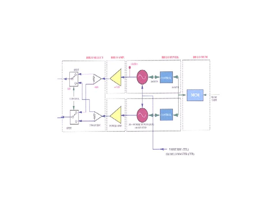
Block Diagram of BBLO system