IF System
175 MHz Conversion
Overview
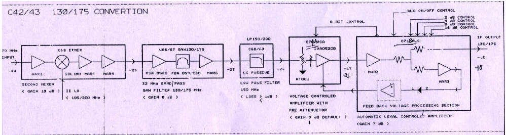
The output of the C-41 PIU is given to the input of C42 & C43 PIU simultaneously.The C-43 PIU acts as a 175 MHz converter converting the 70 MHz frequency signal at its input into 175 MHz signal. Initially it mixes the signal from Local Oscilator 2 by means of a mixer.
Then the signals are fed to a 32 MHz Band pass SAW filter.The Band Pass SAW filter allows a band of frequency 32 MHz to pass. The output of this stage is now fed to a Low Pass Filter. The Low Pass Filter passes al the signals who have the frequency less than 200 MHz. The processed signals are fed to the Voltage Controlled Amplifier with Pre-Attenuator. The gain of this amplifier is 9 dB Default but which can be controlled by using feedback from the next circuit i.e. Automatic Leval Control.
The Automatic Leval Control (commonly refferd as ALC) controls the level of the signal at its input. The gain to be achieved by using ALC can be varied and is set by proper adjustment of 2dB,4dB,8dB, 16dB controls on the control panel. The ALC gives feedback to the preceding stage i.e. Voltage Controlled Amplifier and the gain of amplifier is adjusted to have proper output.
Block Diagram
Mixer
The second Mixer unit converts RF signals into the fixed Fi 175MHz. For this conversion, Amplitude Modulation is used. A device SBL1MH is used for modulation. The SBL1MH is Double Balanced Mixer Module. Amplification of the signal is also done with the help of MAR3 Amplifier. The Mixer module is referred as C65 and named as IIMIX. The default gain of mixer IC is 20dB.
For the datasheet of mixer IC Circuit Diagram
Saw filter bank
The SAW stands for Surface Acoustic Wave. The SAW Filter Bank used in C43 PIU is made for 175MHz.The unit is called as C67.
Some specifications about the 130MHz SAW filter:
- -Insertion loss=26.26 dB
- -Delay=0.517544 microSec
Some of the important characteristics are enlisted below.
Auotomatic Level Controller
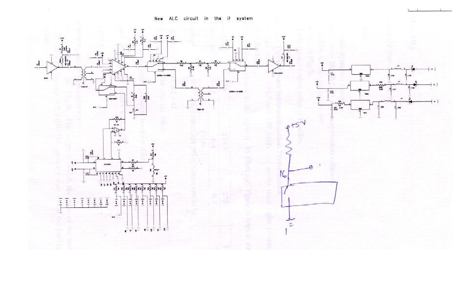
The new design incorporates a new unit AD8367. This device can also used in Variable Gain Amplifier Mode (VGA).
The new ALC circuit has been installed in the IF system.
The ALC IC is in the middle portion of the Gain-Loss Circuit followed by MAR4 amplifier.The Amplifier subsequent to ALC is MSA-0520 which provides the proper operating point, helps in preserving the dynamic range due to its high 1dB compression specification
Some important components used in ALC are enlisted below:
Power Supply
The power supply for the components is generally provided in the chassis itself for the IF system.
Some important components used in Power Supply are enlisted below: