Sentinel System
RF shielding Measurements
GMRT antennas spread over an area of 50 square kilometers. Locally generated RFI are very often appearing in such a vast area that could be seriously affecting to the GMRT Observations. Hence to minimize RFI it is needed a metallic shielded chamber right at the antenna base while processing the Radio signals collected from the sky. GMRT RF Shielded Case is a completely metallic enclosure consists of a door for entry and many holes for cables connected to various sub-system including electrical distribution panels and Air Conditioning systems. To have the better door contact with metallic case, Beryllium coper are fitted on door contact surface to provide better RF shielding. Also the holes made above the metallic case for cables are fitted with Feed-through inside the metallic hat to provide the additional RF shielding.
The following jobs are completed prior to RF shielding measurements.
- 1.Beryllium-coper are fixed in all the antenna shells except very few like C03, C04 and C12. Shri S. Rajamohan took the responsibility for fixing the Beryllium coper in all the antennas,
- 2.For Front-end and Servo system cables Feed-through are fixed on the top of the shielded case covered by a metallic hat. This job is completed only in C09 and W06.
Hence C09 and W01 are presently taken as prototyping antenna for shielding measurement.
RF SHIELDING MEASUREMENT PROCEDURE
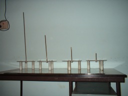
GMRT RF shielding measurements are conducted in the frequency bands of 125, 250, 500 and 1000 MHz. We used two similar kind monopole antennas in each frequency band for transmitting and receiving RF signals. One antenna is placed inside the Shielded Case and connected to the Spectrum Analyzer and other antenna is connected to Signals Generator and placed outside the Shielded Case. The distances between Rx and Tx is about 3 meters along the door side of the Shielded Case. The two measurements are taken when Shielded Case door is opened and closed. Difference between the two measurements gives the shielding effect of the case.
Antenna type : Monopole (for transmitting and receiving)
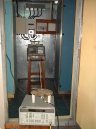
Instruments used:
- 1.HP Spectrum Analyzer, Model- L1500A
- 2.Agilent Synthesized Signals Generator, Model- 8648D
Initially we have tested C09 and W01 as prototyping antenna for shielding measurement. The average shielding effect is about 40 dBm. Also we have measured the shielding for rest of the antennas where only beryllium coper are fixed (but without Feed-through and metallic hat for servo and front-end systems). The results show very poor shielding compare to C09 and W01.