The 610 MHz and 233 MHz feeds are dual frequency coaxial feeds. The single most attractive feature of coaxial waveguide feed is its' multi-frequency launching capability. Simultaneous transmission or reception of well separated frequencies is possible. Coaxial feeds have been used as on board satellite antennas to provide coverage at three separate frequency bands [11]. Coaxial feeds have also been used at the WSRT (operated by NFRA, The Netherlands). The prime focus feed system has at WSRT has two separate multi-frequency coaxial waveguides, covering 327 MHz, 2300 MHz in one and 610 MHz, 5000 MHz in another [12],[13].
The design of the GMRT 610 MHz/233 MHz waveguide feeds is based on an exhaustive theoretical analysis of the design of coaxial waveguide feeds [14],[15]. A constraint in such multi-frequency designs is that adjacent frequency bands should not overlap to within an octave. Thus at the GMRT either the 150 MHz or the 233 MHz could have been combined with 610 MHz. However the former choice was rejected since it resulted in unwieldy dimensions of the feed.
The fundamental mode of propagation in coaxial structures is TEM,
hence the radiated field component along the axis is zero everywhere.
Obviously for a feed this is the most undesirable characteristic. So
propagation by an alternate mode (single or multiple) is essential.
Coaxial waveguides must then be forced to radiate in ![]() mode.
This can be achieved simply by exciting the probes in phase
opposition19.6.
mode.
This can be achieved simply by exciting the probes in phase
opposition19.6.
In the dual frequency construction the outer conductor of the
610 MHz serves as the inner one for the 233 MHz. Quarter wavelength
chokes are provided in both the frequency parts to cut down the surface
currents on the outer conductor and thereby ensure pattern symmetry.
The waveguide feeds have two pairs of probes. One pair supports
a given plane polarization while the orthogonal pair supports
the orthogonal polarization. Similar to the dipole feed discussed in the
previous section, a quadrature hybrid at the back-end of the coaxial
feed is used to convert the linear polarization to circular polarization.
The rear-half of the 610 MHz feed, separated by a partition disc, is
utilized to accommodate the baluns, quadrature hybrids and low-noise
amplifiers of 610 MHz and the baluns of 233 MHz. The overall dimensions
of the feed are given in Table 19.3
|
The phase center is not at the aperture plane, but at a point 60 mm
in front of the aperture. A similar displacement of the phase center
is also seen in the WSRT coaxial feeds [13].
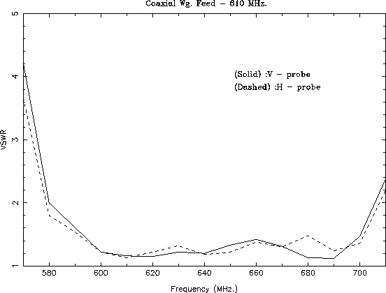
Fig 19.12 shows the VSWR plot for an optimized probe
geometry at 610 MHz For SWR ![]() , the band goes from 580 MHz to
707 MHz, i.e. a total bandwidth of 127 MHz. The feed patterns measured at
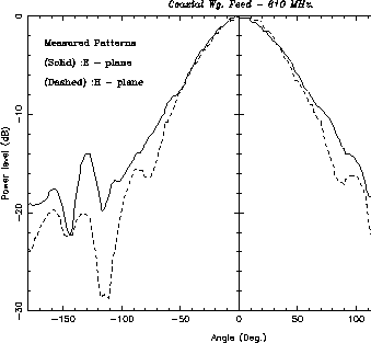
610 MHz are shown in Fig 19.13; the edge taper is
, the band goes from 580 MHz to
707 MHz, i.e. a total bandwidth of 127 MHz. The feed patterns measured at
610 MHz are shown in Fig 19.13; the edge taper is ![]() dB.
The cross-polar maximum is
dB.
The cross-polar maximum is ![]() dB.
dB.
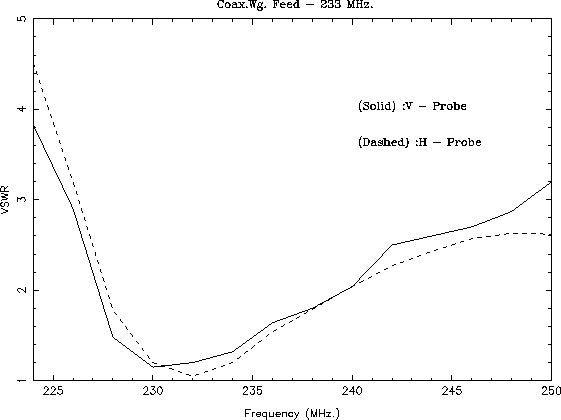
Fig 19.14 shows the VSWR plot of 233 MHz- part of the coaxial feed.
For SWR ![]() , the bandwidth is 12 MHz, i.e. this feed is
rather narrow as compared to all other frequency bands. The effect
of the inter-coupling of radiated power between the two frequencies of
the coaxial feed on the radiation patterns has been studied. The main
lobe does not show any significant change due to the presence of the other
coaxial waveguide part.
, the bandwidth is 12 MHz, i.e. this feed is
rather narrow as compared to all other frequency bands. The effect
of the inter-coupling of radiated power between the two frequencies of
the coaxial feed on the radiation patterns has been studied. The main
lobe does not show any significant change due to the presence of the other
coaxial waveguide part.