A cosmic source typically emits radio waves over a wide range of frequencies, but the radio telescope is sensitive to only a narrow band of emission centered on the RF. We can hence, to zeroth order, approximate this narrow band emission as a monochromatic wave. (More realistic approximations are discussed in Chapter 15). The waves leaving the cosmic source have spherical wavefronts which propagate away from the source at the speed of light. Since most sources of interest are very far away from the Earth, the radio telescope only sees a very small part of this spherical wave front, which can be well approximated by a plane wave front. Electro-magnetic waves are vector waves, i.e. the electric field has a direction as well as an amplitude. In free space, the electric field of a plane wave is constrained to be perpendicular to its direction of propagation and the power carried by the wave is proportional to the square of the amplitude of the electric field.
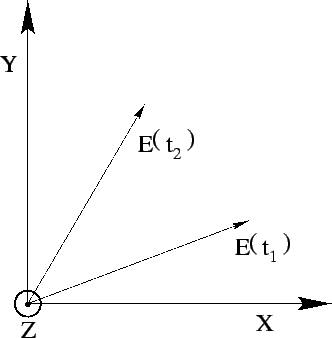
Consider a plane EM wave of frequency ![]() propagating along
the Z axis (Figure 3.6). The electric field then can have
only two components, one along the X axis, and one along the Y axis. Since
the wave is varying with a frequency
propagating along
the Z axis (Figure 3.6). The electric field then can have
only two components, one along the X axis, and one along the Y axis. Since
the wave is varying with a frequency ![]() , each of these components also
varies with a frequency
, each of these components also
varies with a frequency ![]() , and at any one point in space the electric
field vector will also vary with a frequency
, and at any one point in space the electric
field vector will also vary with a frequency ![]() . The polarization
of the wave characterizes how the direction of the electric field vector
varies at a given point in space as a function of time.
. The polarization
of the wave characterizes how the direction of the electric field vector
varies at a given point in space as a function of time.
The most general expression for each of the components of the electric field of a plane monochromatic wave3.2 is:
where
![]() are constants. If
are constants. If ![]() , then
the field only has one component along the X axis, which increases in
amplitude from
, then
the field only has one component along the X axis, which increases in
amplitude from ![]() to
to ![]() and back to
and back to ![]() over one period.
Such a wave is said to be linearly polarized along the X axis.
Similarly if
over one period.
Such a wave is said to be linearly polarized along the X axis.
Similarly if ![]() is zero then the wave is linearly polarized along the
Y axis. Waves which are generated by dipole antennas are linearly
polarized along the length of the dipole. Now consider a wave for which
is zero then the wave is linearly polarized along the
Y axis. Waves which are generated by dipole antennas are linearly
polarized along the length of the dipole. Now consider a wave for which
![]() , and
, and
![]() . If we start at a
time at which the X component is a maximum, then the Y component is zero
and the total field points along the +X axis. A quarter period later, the
X component will be zero and the Y component will be at maximum, the total
field points along the +Y direction. Another quarter of a period later,
the Y component is again zero, and the X component is at minimum, the
total field points along the -X direction. Thus over one period, the tip
of the electric field vector describes a circle in the XY plane. Such a
wave is called circularly polarized. If
. If we start at a
time at which the X component is a maximum, then the Y component is zero
and the total field points along the +X axis. A quarter period later, the
X component will be zero and the Y component will be at maximum, the total
field points along the +Y direction. Another quarter of a period later,
the Y component is again zero, and the X component is at minimum, the
total field points along the -X direction. Thus over one period, the tip
of the electric field vector describes a circle in the XY plane. Such a
wave is called circularly polarized. If ![]() were
were ![]() then the electric field vector would still describe a circle in the
XY plane, but it would rotate in the opposite direction. The former is
called Right Circular Polarization (RCP) and the latter
Left Circular Polarization (LCP).3.3 Waves generated by Helical antennas
are circularly polarized. In the general case when all the constants have
arbitrary values, the tip of the electric wave describes an ellipse
in the XY plane, and the wave is said to be elliptically polarized.
then the electric field vector would still describe a circle in the
XY plane, but it would rotate in the opposite direction. The former is
called Right Circular Polarization (RCP) and the latter
Left Circular Polarization (LCP).3.3 Waves generated by Helical antennas
are circularly polarized. In the general case when all the constants have
arbitrary values, the tip of the electric wave describes an ellipse
in the XY plane, and the wave is said to be elliptically polarized.
Any monochromatic wave can be decomposed into the sum of two
orthogonal polarizations. What we did above was to decompose a circularly
polarized wave into the sum of two linearly polarized components. One could
also decompose a linearly polarized wave into the sum of LCP and RCP waves,
with the same amplitude and ![]() radians out of phase. Any antenna is
sensitive to only one polarization (for example a dipole antenna only
absorbs waves with electric field along the axis of the dipole, while
a helical antenna will accept only one sense of circular polarization).
Note that the reflecting surface of a telescope could well 3.4 work for both polarizations, but the feed antenna will respond
to only one polarization. To detect both polarizations one need to put
two feeds (which could possibly be combined into one mechanical
structure) at the focus. Each feed will require its own set of electronics
like amplifiers and mixers etc.
radians out of phase. Any antenna is
sensitive to only one polarization (for example a dipole antenna only
absorbs waves with electric field along the axis of the dipole, while
a helical antenna will accept only one sense of circular polarization).
Note that the reflecting surface of a telescope could well 3.4 work for both polarizations, but the feed antenna will respond
to only one polarization. To detect both polarizations one need to put
two feeds (which could possibly be combined into one mechanical
structure) at the focus. Each feed will require its own set of electronics
like amplifiers and mixers etc.
EM waves are usually described by writing explicitly how the electric
field strength varies in space and time. For example, a plane wave of
frequency ![]() and wave number
and wave number ![]() (
(
![]() )
propagating along the Z axis and linearly polarized along the X axis
could be described as
)
propagating along the Z axis and linearly polarized along the X axis
could be described as