The Giant Metrewave Radio Telescope (GMRT) consists of a
distributed array of antennas all connected to a Central Electronics
Building (CEB) via optical fiber links. Optical fibers are superior
to the more traditional co-axial cables or waveguides in a variety
of respects. Optical fibers have lower transmission losses, higher
bandwidth and have better isolation against radio frequency
interference. More quantitatively, while the loss in co-axial cables
are several 10 s of dB/km, the loss in optical fibers is as low as
0.2 dB/km. Further 100 GHz-km bandwidths are routinely achievable
in single mode optical fibers, while the achievable bandwidth for
co-axial cables is only ![]() MHz-km.
MHz-km.
The optical fiber link between the CEB and a given antenna has two major functions:
 |
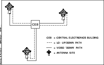
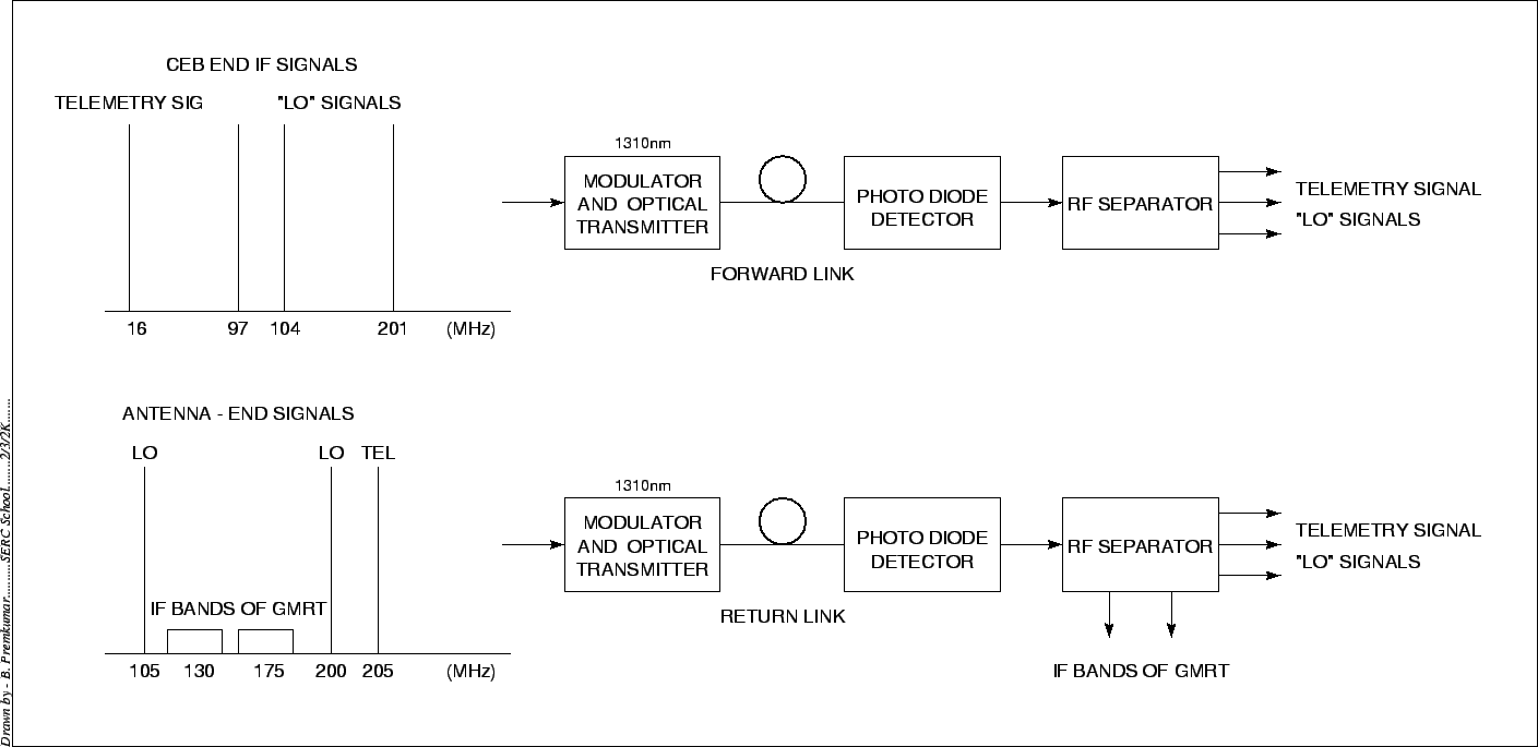
As shown in Figure 22.1 there are two fibers between each antenna and the CEB, one of which forms part of the forward link and carries the control and LO signals to the antenna, and the other of which forms part of the return link and carries the astronomical signal (at the IF frequency, see Chapters 21, 23) and the monitoring data (also referred to as telemetry data) and the return LO22.1 back to the CEB. Each link consists an optical transmitter (a laser diode) the fiber itself (which is a single mode glass fiber), and a receiver (a photo diode). A block diagram of the GMRT optical Link is show in Figure 22.2 and the frequencies of the different signals that are transported by the link are also indicated. We now discuss the various elements of the GMRT optical link in some more detail.
 |