 |
Chapters 8 and 9 covered the basics of correlator design and implementation. Recall that there are two popular types of correlators, viz. the FX and XF types. The FX design has a number of advantages including (a) low cost, (b) digital fringe stopping and fractional delay compensation and (c) minimal closure errors. The GMRT correlator is an FX correlator. The integrated circuit (IC) used for performing the FFT and the correlation is an application specific IC (ASIC) designed by the NRAO for the VLBA correlator. This chapter provides an overview of the GMRT correlator and discusses its various modes of operation. The material is meant as a guide the correlator users (i.e. astronomers). For details of hardware implementation see Tatke (1997).
The main considerations while designing the GMRT correlator were the following:
The last two requirements favor an FX configuration. Since the FX correlator inherently measures the visibility spectrum, any narrow band RFI can be edited out. To improve the dynamic range 4-bit sampling is used.
 |
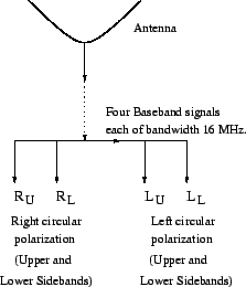
Recall that the GMRT has 30 antennas and that each antenna
provides signals in two orthogonal25.1 polarizations. The maximum
operating bandwidth at all frequency bands is 32 MHz, which is
provided as two 16 MHz wide baseband signals (corresponding to the
two sidebands) for each polarization (see Fig. 25.1).
From the basic block diagram of an FX correlator (see Fig 9.4
in Chapter 9) it is evident that the GMRT
correlator should have
![]() ADCs, integral
delay compensation units, number controlled oscillators, FFTs
and fractional delay compensation units.
ADCs, integral
delay compensation units, number controlled oscillators, FFTs
and fractional delay compensation units.
The total number of multiplier units required for the GMRT can
be calculated as follows. The total number of cross products for a
![]() element array is
element array is
![]() . If the self products are also
computed then the total number of products is
. If the self products are also
computed then the total number of products is
![]() .
In an FX correlator these products have to be measured for each
spectral channel. Since the GMRT correlator provides 256 spectral
channels, the total number of multiplier units required is
.
In an FX correlator these products have to be measured for each
spectral channel. Since the GMRT correlator provides 256 spectral
channels, the total number of multiplier units required is
![]() . Further since, as discussed above,
there are four baseband signals for each antenna, the number of
multiplier units required goes up by a factor of 4. To measure
all the four Stokes parameters the cross products between different
polarizations need to be measured (see chapter 15),
this causes the required number of multiplier units to increase
by another factor of 2. Thus for
. Further since, as discussed above,
there are four baseband signals for each antenna, the number of
multiplier units required goes up by a factor of 4. To measure
all the four Stokes parameters the cross products between different
polarizations need to be measured (see chapter 15),
this causes the required number of multiplier units to increase
by another factor of 2. Thus for ![]() the total number of
multipliers required is 9,52,320. However, to lower the cost and to
simplify the hardware design the number of multiplier units in
the GMRT correlator is only 2,38,080. To minimize the impact
of this reduction in multipliers, the GMRT correlator has a
a highly configurable design. Depending on the astronomical requirement
the correlator can be configured to minimize the loss of information,
for example in may spectral line observations it is not neccessary
to measure all four stokes parameters. The following sections
give an overview of the GMRT correlator and also discuss these
different correlator configurations.
the total number of
multipliers required is 9,52,320. However, to lower the cost and to
simplify the hardware design the number of multiplier units in
the GMRT correlator is only 2,38,080. To minimize the impact
of this reduction in multipliers, the GMRT correlator has a
a highly configurable design. Depending on the astronomical requirement
the correlator can be configured to minimize the loss of information,
for example in may spectral line observations it is not neccessary
to measure all four stokes parameters. The following sections
give an overview of the GMRT correlator and also discuss these
different correlator configurations.